

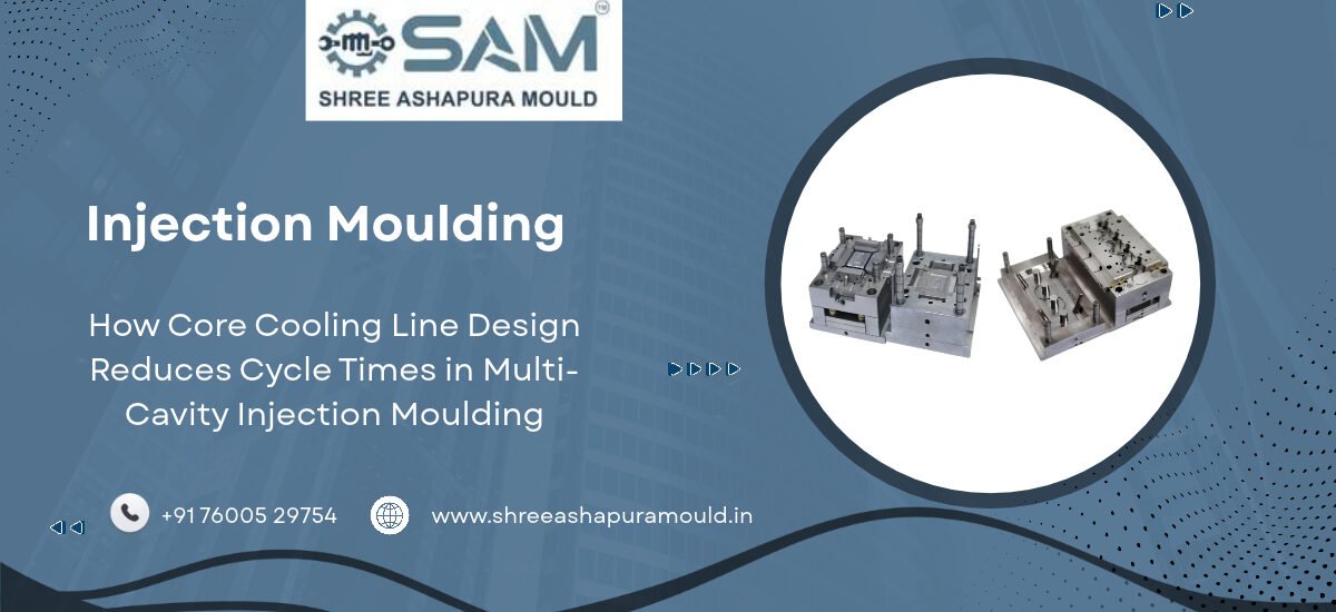
How Core Cooling Line Design Reduces Cycle Times in Multi-Cavity Injection Moulding
In high-speed PET preform injection moulding, cooling accounts for more than 60% of the total cycle time. Because thick-walled plastic preforms retain significant heat from the melt phase, the core pin must rapidly extract thermal energy from the inner resin wall so the part can be ejected without distortion, sink marks, or sticking.
If core cooling is slow or uneven, plant operators are forced to extend the cooling phase, directly increasing cycle time and reducing total daily output. Furthermore, inadequate heat removal leads to preform shrinkage, neck warping, and internal thermal stress that causes failures during stretch blow moulding.
Optimizing core cooling circuit design is the single most effective way to reduce cycle times while maintaining strict dimensional tolerances in multi-cavity PET tooling.
Key Engineering Strategies for Core Cooling Optimization
1. High-Flow Bubbler and Baffle Systems
Standard straight-drilled cooling channels are insufficient for deep preform core pins. Modern tools utilize internal bubbler tubes or spiral baffles:
Bubbler Circuitry: Chilled water travels up a central tube directly to the tip of the core pin—the hottest zone of the tool—and cascades down the outer channel wall back to the return manifold.
Spiral Flow Channels: Helical grooves machined into inner core inserts force coolant to swirl around the core perimeter, maximizing fluid surface contact area and thermal transfer rates.
       [ Chilled Water In ]
               |
        +------+------+
        |  Bubbler    |  --> Direct cooling to Core Tip
        |   Tube      |
        +------+------+
               |
       [ Heat Dissipation Out ]
2. Maintaining Turbulent Fluid Flow (Reynolds Number > 4,000)
Laminar water flow (smooth, slow movement) creates an insulating boundary layer of warm water along the inner channel wall, slowing down heat absorption.
To break this insulating layer, cooling systems must maintain turbulent flow with a Reynolds Number ($Re$) exceeding $4,000$. Achieving turbulent flow requires:
High coolant supply pressure ($4\text{ to }6\text{ bar}$).
Adequate flow rate volume through manifold supply lines.
Smooth, unrestricted internal channel geometry free of sharp restrictions or tight elbows.
3. Utilizing Beryllium-Copper (BeCu) or Beryllium-Free High-Conductivity Alloys
While stainless steel cavity plates offer strength and corrosion resistance, tool steel has relatively low thermal conductivity ($\approx 15\text{ to }25\text{ W/m}\cdot\text{K}$).
Incorporating high-conductivity inserts (such as Beryllium-Copper alloys with thermal conductivity around $100\text{ to }130\text{ W/m}\cdot\text{K}$) into the core tip speeds up localized heat dissipation by up to 300%, allowing dramatic cycle time reductions without sacrificing core strength.
Related Precision Tooling Solutions
Upgrade your plant efficiency with our advanced PET Preform Mould systems engineered with high-flow core cooling technology.
Producing wide-mouth containers? Read our technical recommendations for PET Jar Mould cooling layouts.
Complement your preform line with precision-cooled PP Cap Mould tooling for fast closure production.





 Users Today : 2
 Users This Month : 8
 Total Users : 9