

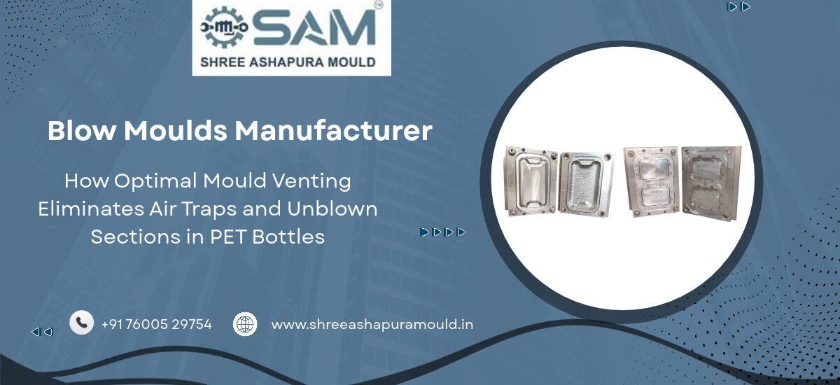
How Optimal Mould Venting Eliminates Air Traps and Unblown Sections in PET Bottles
In stretch blow moulding, high-pressure compressed air rapidly inflates a heated PET preform inside the closed cavity. As the preform expands outward toward the cavity walls, the ambient air occupying the cavity space must be displaced instantly.
If the mould design does not provide adequate cavity exhaust channels, ambient air becomes trapped between the expanding hot plastic film and the cold tool steel wall. This trapped air creates localized pressure pockets that resist full expansion, leading to unblown bottle details, thin wall zones, poor logo definition, and burn marks caused by compression heating.
Engineering a balanced micro venting system across parting lines, engraving features, and base inserts is essential for producing high-clarity PET containers with crisp structural details.
Physics of Air Displacement During Stretch Blowing
During high-speed stretch blow moulding, preform inflation occurs in two sequential steps: pre-blowing at lower pressure followed by main blowing at high pressure. The entire inflation sequence completes within fractions of a second.
Air Compression Dynamics: As the expanding PET membrane moves toward the cavity surface, atmospheric air trapped inside the sealed cavity undergoes rapid adiabatic compression.
Thermal Resistance Layer: Compressed trapped air forms an insulating barrier, preventing direct contact between the PET material and the water-cooled cavity surface.
Pressure Resistance: If trapped air pressure equals internal blowing pressure, the PET film stops expanding, leaving rounded bottle corners, shallow structural ribs, and unblown base feet.
Key Mould Venting Engineering Strategies
1. Parting Line Micro Venting Grooves
The primary air evacuation path in a blow mould is located along the main vertical parting line where the two cavity halves meet.
Depth Precision: Micro venting grooves are precision-ground along the parting line perimeter. The groove depth must be large enough to evacuate air rapidly, yet shallow enough to prevent molten plastic from entering and creating visible seam lines on the finished bottle.
Relief Channels: Micro vents feed directly into wider primary exhaust channels machined behind the parting face, allowing compressed air to vent freely into the atmosphere.
2. Porous Metal Inserts for Complex Engravings
Intricate structural details—such as brand logos, panel ribs, and grip patterns—create localized pockets where air cannot reach the perimeter parting line.
Micro-Porous Steel Sintering: Toolmakers integrate porous metal inserts made of sintered stainless steel inside deep logo recesses or structural ribs. These inserts contain microscopic interconnected pores that allow air to pass through while presenting a smooth surface to the expanding PET material.
Vacuum Assistance Interfacing: Porous inserts can be connected to external vacuum assistance systems to pull the PET film tight against complex embossing profiles.
3. Base Cup Venting and Exhaust Pins
The bottom section of a PET bottle features complex petaloid base geometry designed to withstand internal pressure. Because the base is the last section reached by the expanding preform wall, air traps in the base cause structural instability.
Exhaust Pin Slots: Base inserts incorporate spring-loaded or stationary venting pins with narrow annular clearances around their perimeter.
Radial Base Channels: Radial evacuation grooves machined across the base plate ensure air escapes from every petaloid valley during final high-pressure expansion.
Summary of Venting Specifications and Defect Prevention
Unblown Panel Ribs: Resolved by adding micro venting slots directly along rib apexes to prevent compressed air pockets.
Distorted Brand Logos: Corrected through micro-porous steel inserts positioned behind complex letter contours.
Rocking Bottle Base: Fixed by expanding radial base exhaust slots to ensure complete petaloid formation.
Surface Haze and Burn Marks: Prevented by continuous parting line exhaust channels that eliminate adiabatic air compression heating.
Related Precision Tooling Solutions
Looking for precision blow tooling? Explore our complete Blow Mould manufacturing configurations engineered with optimized micro venting systems.
Need high-cavity preform tooling? Learn about our advanced PET Preform Mould product line.
Complete your container line with custom-engineered PP Cap Mould solutions.



 Users Today : 6
 Users This Month : 180
 Total Users : 242